Location
Zhenjiang, Jiangsu, China

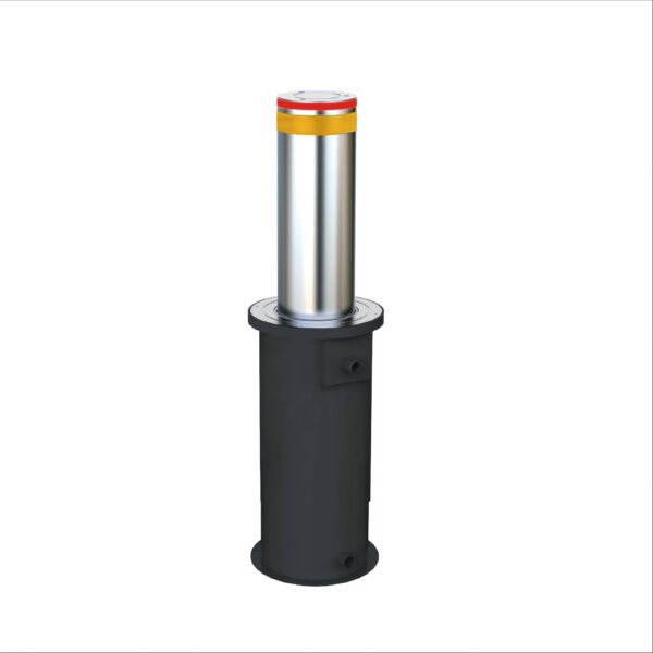
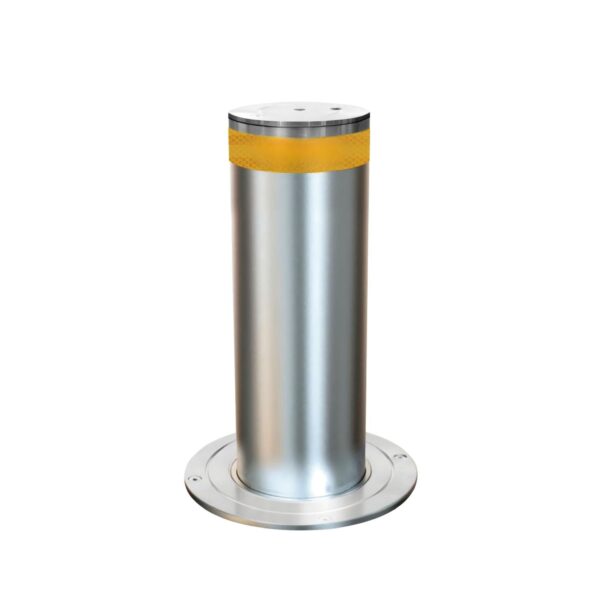
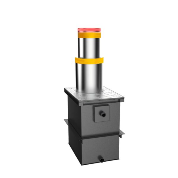
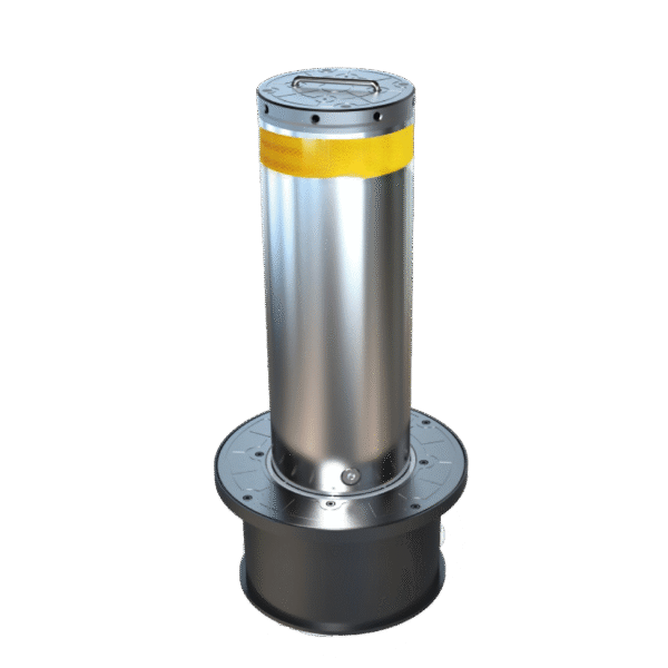
600mm 50t Hydraulic Rising Bollard BS-SY602R-406
304 stainless steel hydraulic rising bollard with 600mm raised height, 150mm/s movement, 50-ton passing load, warning light and backup-powered lowering.
Description
Direct Answer
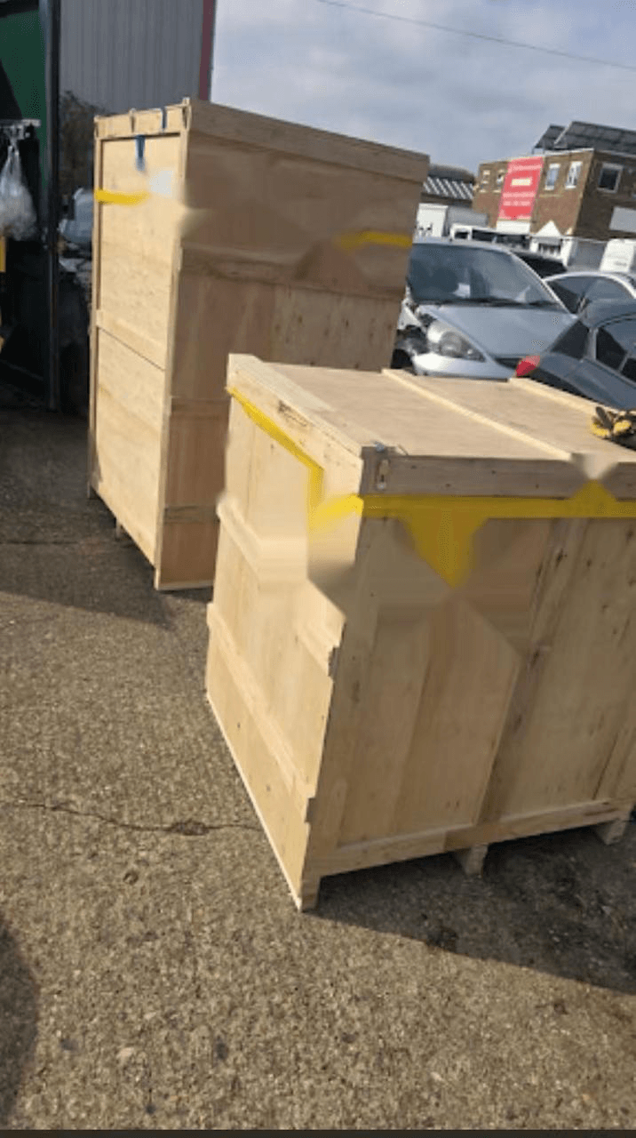
BS-SY602R-406 is an IP68 hydraulic rising bollard for high-security vehicle access projects. BAISEN recommends a 6mm wall thickness for this model’s 1.2m column assembly. Control components can be factory pre-wired to the confirmed project configuration for faster site commissioning. Each export order is prepared with reinforced wooden-crate protection to reduce handling damage during international delivery.
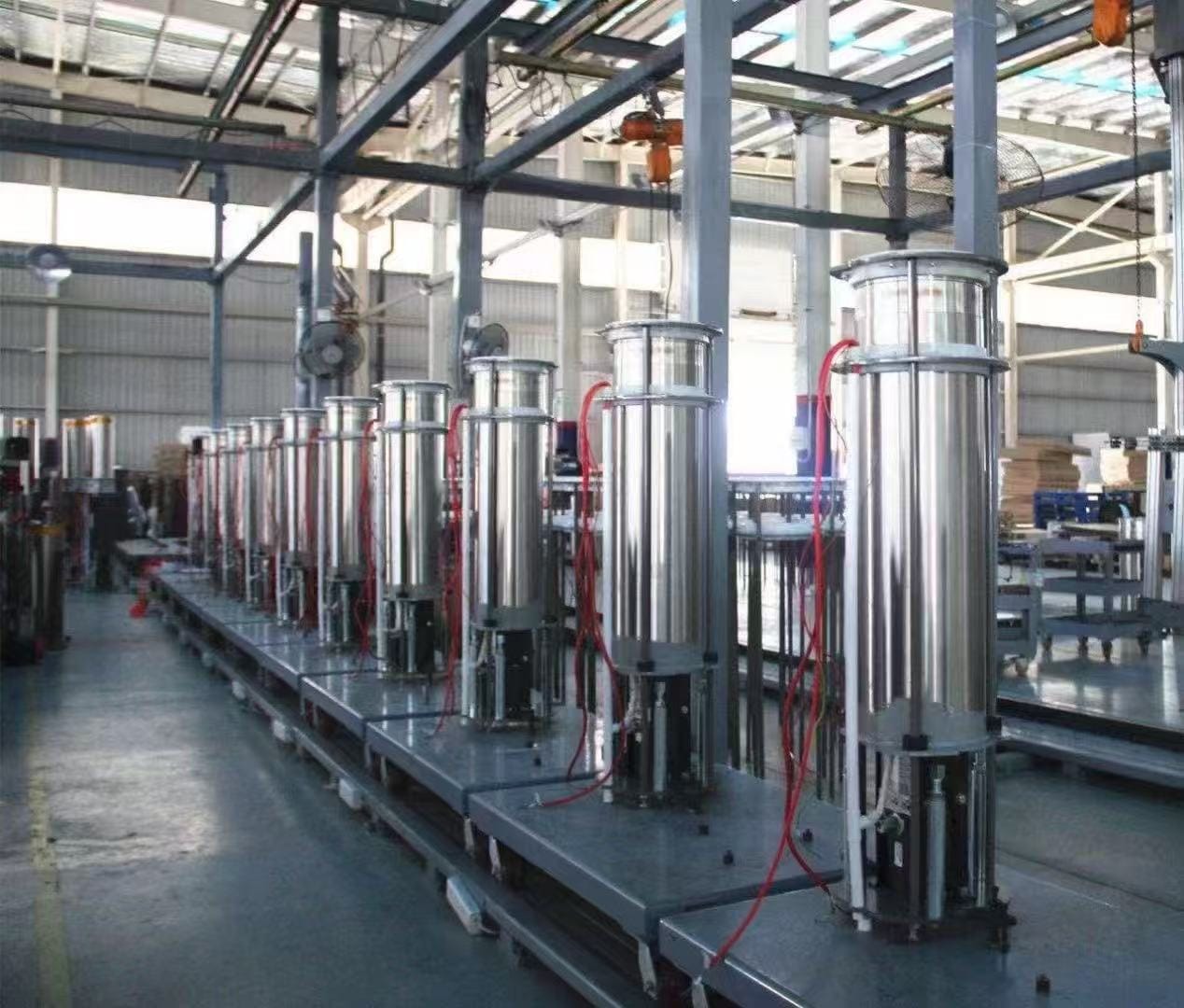
Factory Inspection & UK Delivery Protection
Installation Support
Automatic Hydraulic Bollard Technical FAQ
Foundation, drainage and field-wiring guidance for system integrators and installation contractors.
What foundation and civil work are required for installing automatic hydraulic bollards?
For this automatic hydraulic bollard, prepare a foundation pit approximately 800mm wide and 1300mm deep, including a 200mm compacted foundation or drainage layer. After positioning and levelling the bollard, secure and backfill the surrounding area, then cast the upper 300mm with C25-grade concrete or higher. Finish the bollard flange 3-5mm above the surrounding ground and confirm final civil dimensions against the approved model drawing and site conditions.
How do you handle drainage in areas with heavy rain or high groundwater?
Drainage must be selected according to the site survey. Natural seepage uses a compacted crushed-stone and sand layer beneath the bollard, with a 50mm PVC elbow directing water into the drainage layer. Where suitable, the bottom 50mm PVC outlet may connect to the approved stormwater network. For low-lying, flood-prone or poorly drained sites, install a separate collection sump with an automatic submersible pump and discharge it to an approved drain or landscaped area.
Are the electrical cables difficult to wire on-site?
No. The bollard uses a prepared external junction box so site contractors do not need to wire inside the bollard casing. The installation manual specifies one 3-core 2.5mm² motor cable. The LED and solenoid-valve signal cable is 4-core 1.0mm². All cable joints must receive proper waterproof insulation before being routed through conduit to the control cabinet.
Pre-Installation Checklist
Engineering Site Survey & Buyer’s Guide
Review these civil, drainage and electrical requirements before confirming the bollard configuration, control cabinet position and installation plan.
Step 1: Civil Pit & Drainage Survey
Verify the groundwater level and choose between natural seepage, a municipal drainage outlet, or an automatic sump pump system. For this automatic hydraulic bollard, prepare an installation pit approximately 800mm wide and 1300mm deep, including an approximately 200mm foundation and drainage layer.
Step 2: Electrical & Cable Trenching
Route one 3-core 2.5mm² motor power cable and one 4-core 1.0mm² LED/solenoid-valve signal cable directly from the installation pit to the PLC control cabinet.
Step 3: Foundation Concrete Standard
Prepare the approximately 200mm foundation and drainage layer, position and level the bollard casing, and complete the upper approximately 300mm section with C25-grade concrete or higher. Keep the finished bollard flange approximately 3–5mm above the surrounding surface to reduce dust and surface-water accumulation.
Engineering note: Final pit dimensions, drainage design and cable routing must be verified against the approved project drawing and local site conditions before construction begins.